 Back
Back
Older F650 info:
NOTE: The older F650 has different shim and bucket mechanism than the G650X. The cam chain tensioner might also work differently (and possibly other things) so keep this in mind when you read the F650 specific steps. YMMV.
-Torx T25 Security bit for removing throttle cable bracket screws (recommended but optional):
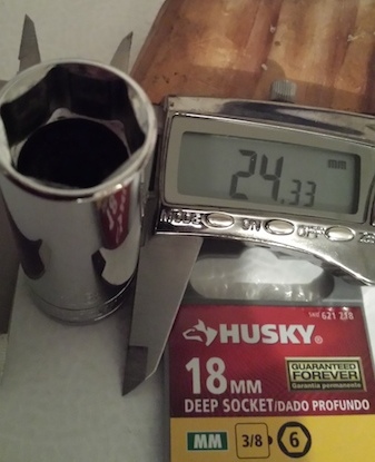
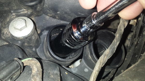
-Thinwall 18mm deep socket for spark plug. You can do so after you remove the valve cover, but if you want to remove a spark plug on the road you will need a VERY thin wall to fit through the valve cover hole, as many are too thick. (Tip: also insert some foam/rubber inside it to grab plug). One 18mm deep socket that fits as it is only 24.33mm wide is the Husky brand SKU# 621718 from Home Depot:
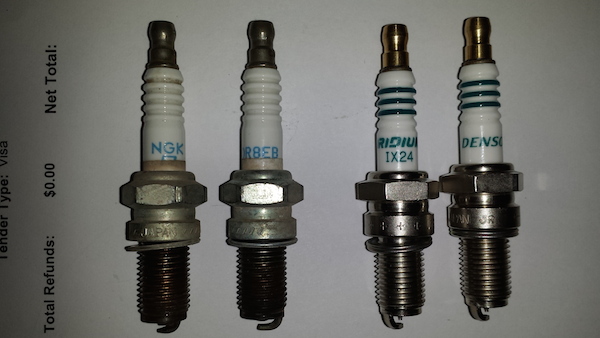
-Optionally you may want to install higher performance Iridium spark plugs. I installed what many recommended, the Denso IX24 Iridium Power spark plug. Here they are vs. the stock NGK DR8EB:
-TDC bolt, only really needed for adjusting not just checking clearance. See Reference 5 the F650.com FAQ which has directions on how to make your own.
Now I will just go over the steps I found tricky and a few pics but not showing every single step:
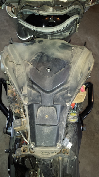
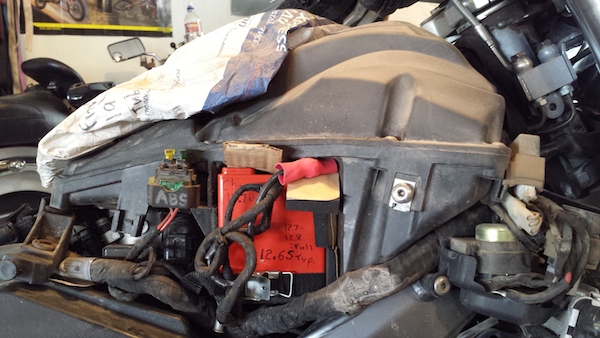
1. Remove all the side plastics and battery, and you are ready to remove the airbox from the engine, but don't do it yet. You don't need to separate the airbox into top and bottom halves (unless you want to clean it out):
But BEFORE you start to remove the airbox, notice how far down onto the throttle body the airbox sits, so you know how it should look when you install it later:
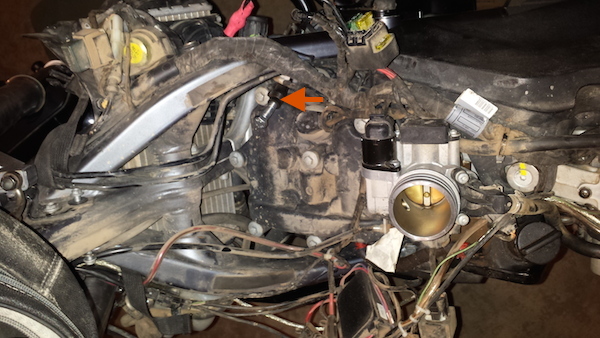
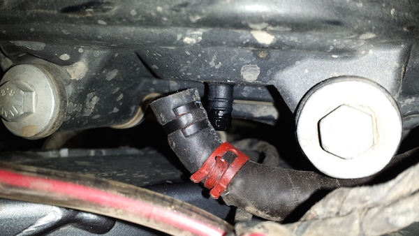
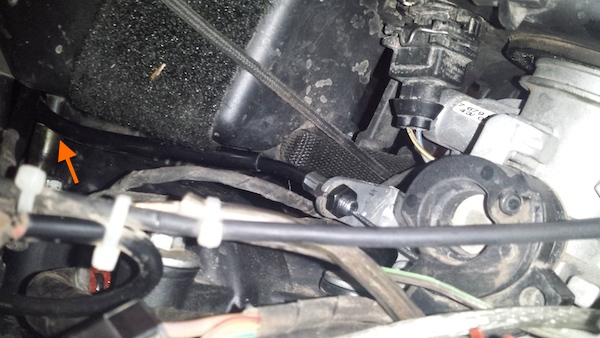
2. When you pull off the airbox, one last troublesome hose that holds it down is the breather hose on the bottom of the front right corner of the airbox. Normally you pull off the bottom of this hose at the engine block but I didn't want to remove my aftermarket skidplate to access it, so I carefully pried off the top end at the airbox itself. This will be very difficult to re-insert later so I re-routed the hose to get a little more slack in it. You can see it in the following picture with the airbox removed, it has a bolt inserted into the end of it:
3. To keep the throttle body protected, stuff a rag and/or cover with a plastic bag. Now you will want to remove the throttle cable from the throttle bracket on the throttle body and also to give the valve cover more clearance for removal I also removed the Torx T25 Security screws and removed the bracket as well:
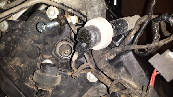
4. Pull both coil sticks off of the spark plugs. Be very careful as they break easily, use a lot of twisting and wiggling. Black top is primary one and goes on the inside. Grey top is secondary one and goes on the outside (it also has some white tape on the wires into it):
5. You can leave the spark plugs until later, but if you want to make sure your 18mm spark plug socket is thin enough to fit into the hole in the valve cover for use on the road, now is the time to try it out. Here is the Husky socket I referred to earlier:
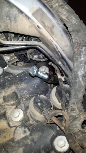
6. Pull off the breather hose on the left side of the valve cover (often this rubber hose is cracked and needs replacing, I used fuel hose and a "spring (constant tension) clamp"). Carefully, the valve cover is not metal so not that strong.
7. Now you can remove the valve cover. Note that the bolts can be held captive in the cover with their rubber sleeves holding them in so you can leave them in the cover when you remove the cover. Now you see the camshafts and cam chain, etc:
8. Remove or at least loosen the primary spark plug to allow the engine to rotate more easily.
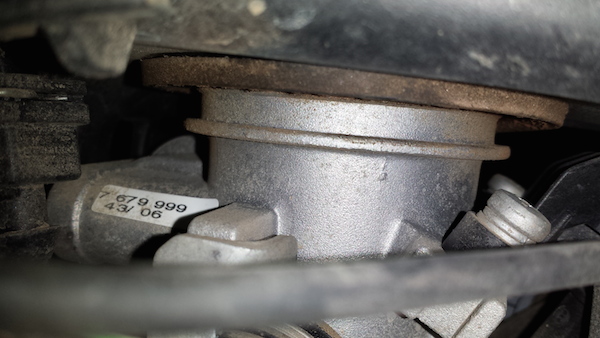
9. Now you need a way to rotate the engine crankshaft. You can either put it in gear and rotate the rear wheel OR more controlled is to remove the soft plug in the right side magneto cover (use a 9/16" hex wrench) then insert an 8mm hex wrench (and cheater pipe) into the cover into the end of the crank shaft to rotate it.
Now the preparations are done and it is ready for the actual procedure to check the valve clearances:
10. Rotate the engine crankshaft until the indicator lines on both cam gears are horizontal AND all 4 camshaft lobes are pointing outwards, per the instructions in References 1 (REPROM) or 5 (F650.com).
You don't need a TDC bolt (Top Dead Center) if you pay attention (as I would have to make one, PLUS my skidplate would have to be removed to insert it).
As a double check, you can verify it is at TDC (rather than Bottom Dead Center) by removing the innermost spark plug and putting a long screwdriver in it and watch it move up and down.
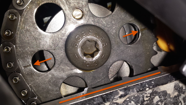
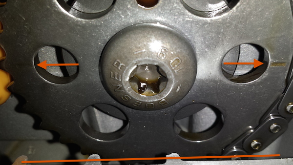
Difficult to take, but these pics try to show the TDC indicator lines are horizontal on the Front (Exhaust) and Rear (Intake) cam gears, respectively:
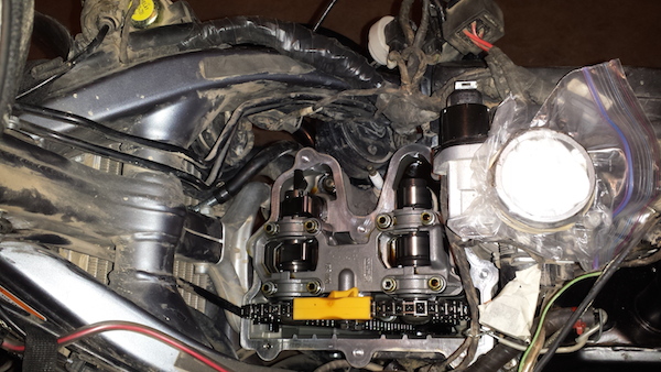
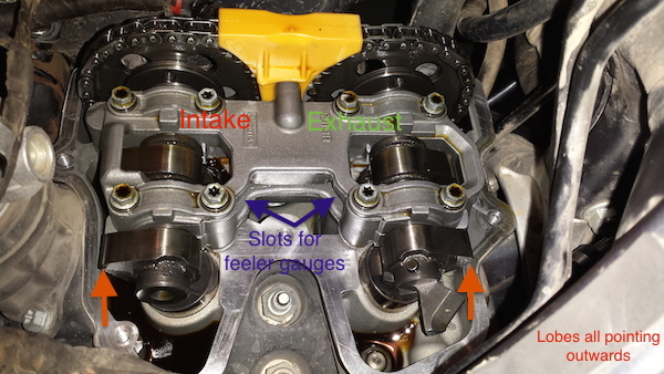
This pic shows the camshaft lobes are pointing outwards (away from each other):

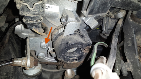
11. The Intake valves are towards the rear and the Exhaust valves are towards the front. The 2 on the left side of the engine (nearest the cam chain) have little slots for inserting the feeler gauges in:
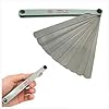
Make sure the engine is cold and measure the clearances with the feeler gauges, they must fall within these specs:
Intake: 0.03 to 0.11 mm
Exhaust: 0.25 to 0.33 mm
I checked mine at 23,000 miles and they were all ok (in mm): Intake: L: .05, R: .05. Exhaust: L: .32, R: .325.
12. If yours are out of spec then you need to adjust them by changing a shim. I have never done this but if I was going to do the Adjustment I would follow the Alternate Method from F650.com in Reference 5 above (also see video in Reference 6).
13. Now is the time to change the spark plugs if so inclined (as I said earlier, I installed new "Denso IX24 Iridium" plugs. Torque to 23 Nm (200 in-lbs) (which feels like a LOT!).
Finished with the valve clearance so now just put it all back together:
14. Install valve cover, torque bolts to 10 Nm (88 in-lbs).
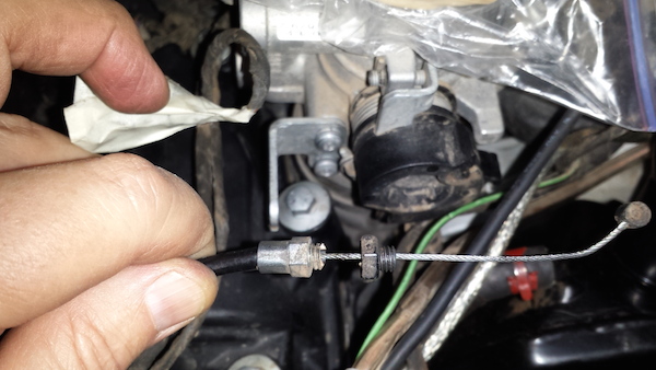
15. When re-installing the throttle cable and tightening the nut at the throttle bracket, don't do what I did and over tighten the nut on the cable! The threaded cable end is very soft and will shear off:
16. It seemed to me that the throttle cable must be routed to the OUTSIDE of the clear oil drain hose coming down from the battery box (bottom of airbox on left side), or else it will end up on the top of the valve cover and prevent the airbox from fully going DOWN onto the throttle body properly:
17. Don't forget to attach the breather hose on the front right corner of the airbox as you install it. If your airbox is installed properly and is fully DOWN onto the throttle body then this is the small gap you should see:
18. Finish installing connectors, bolts, covers and you are done. I carry a spare front inner tube (could work on rear in a pinch) above the airbox under the XCountry faux gas tank cover, in a U.S. Postal envelope (free, made of Tyvek, tough stuff):
NOTE: I also did not like how much the electrical cable harness rubbed between the corner of the airbox and the right side cover (near the battery, see above photo). So I decided to cut off about 0.5" off of the corner to give the cable bundle more room. This is documented in my Airbox Mod.
YOU ARE DONE!
APPENDIX:
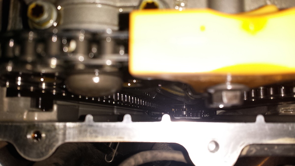
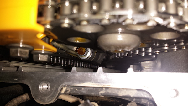
Here are a couple more photos that might come in handy if you have to adjust the valves using the zip tie method. They are taken looking straight down to see the cam chain mechanism and chain tightener (on the right side of picture):
Back